termoDaQ
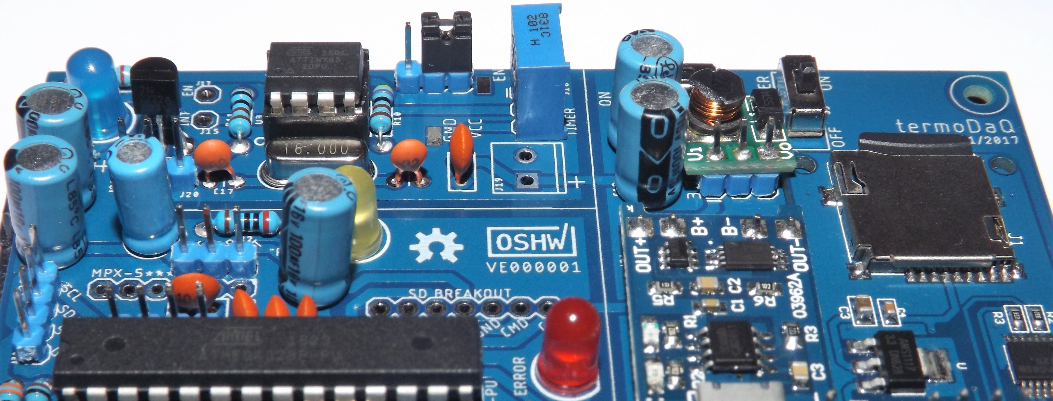
termoDaQ is a development board based on the Arduino architecture, uses an ATmega328-P and an ATtiny85 for its operation.
This board was originally designed to help the work of oceanography students, serving as an instrument for the acquisition of physical variables (temperature, pressure) at surface level in bodies of fresh water, in order to detect changes that may affect the flora or fauna of ecosystems, automating the work of making measurements over time.
But it can serve many purposes since it has a connection for GPS receivers, pressure sensor, multiple temperature sensors (internal and external), two additional inputs for any analog sensor (such as rain, flow or UV) and SD card.
The function of the ATtiny85 is work as a timer to program the operation cycles of the equipment, reducing the energy consumption, which allows incrementing the operation time when the battery is used. To achieve this, activate and deactivate the sensors area.
The function of the ATmega328-P is to control the sensors area, managing each of them to perform the measurement and data storage processes.
Operation

The board is divided into three parts
1) Power supply. 2) Energy management. 3) Sensors area.
In particular, I’m responsible for developing the energy management and the sensors area.
For the energy management, is used the ATtiny85 microcontroller to carry out cycles that enable or disable the sensors, cutting off the power in periods where no measurements are needed.
As for the sensors area, its function is to perform the measurements and store the data. Only one cycle at a time, at the end one signal is sent to the energy management area to cut the power.
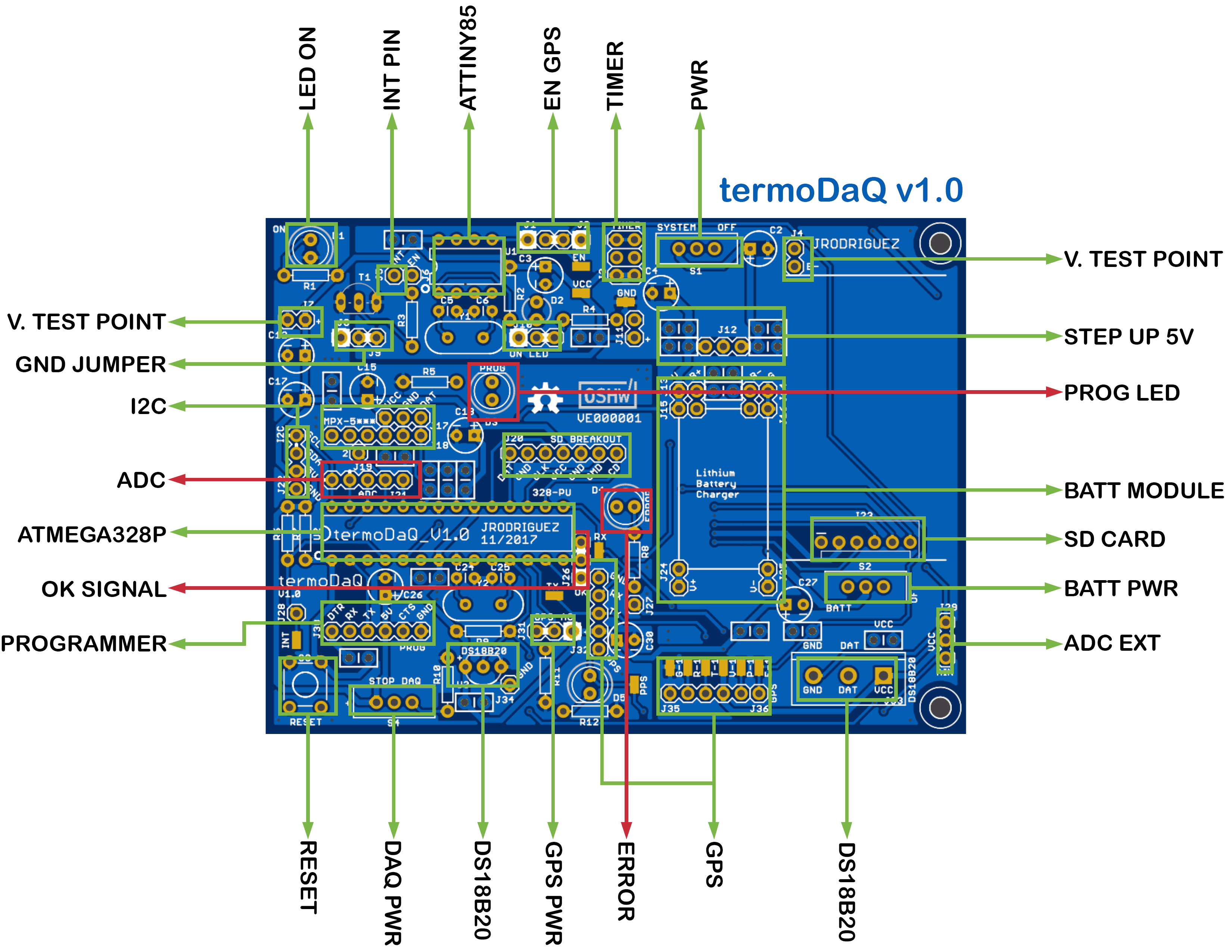
Pinout
Board specifications
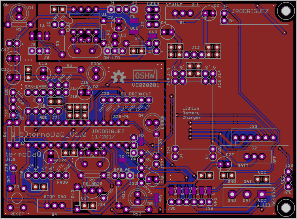
All the source files are in this repository
- Board Size: 99.82 mm X 73.41 mm (X = 99.82, Y = 73.41)
- Number of layers: 2
- Number of drills: 311
- Number of vias: 47
- Number of signals: 146
- Minimum copper trace width: 0.41 mm
- Consumption: ~ 80mAh (currently under test)
ATtiny85
| Name | Value |
|---|---|
| Operating Voltage Range (V) | 1.8 to 5.5 |
| Temperature Range (C) | -40 to 85 |
| CPU Speed (MIPS/DMIPS) | 20 |
| Pin Count | 8 |
| Program Memory Type | Flash |
| Program Memory Size (KB) | 8 |
| SRAM Bytes | 512 |
| Data EEPROM/HEF (bytes) | 512 |
| Digital Communication Peripherals | 1-SPI, 1-I2C |
| Capture/Compare/PWM Peripherals | 5PWM |
| Timers | 2 x 8-bit |
| Number of Comparators | 1 |
ATmega328P
| Name | Value |
|---|---|
| Operating Supply Voltage | 1.8 V to 5.5 V |
| Temperature Range (C) | - 40 to 85 |
| Maximum Clock Frequency | 20 MHz |
| Pin count | 28 |
| Number of I/Os | 23 I/O |
| Program Memory Type | Flash |
| Program Memory Size | 32 kB |
| Data Bus Width | 8 bit |
| Data RAM Type | SRAM |
| Data RAM Size | 2 kB |
| Data ROM Type | EEPROM |
| Data ROM Size | 1 kB |
| Number of ADC Channels | 6 |
| ADC Resolution | 10 bit |
| Interface Type | I2C, SPI, USART |
| Number of Timers/Counters | 3 Timer |
Translation
English translation using google translator.
If you wish, you can help me translate the readme file correctly.
License
Creative Commons Attribution-ShareAlike 4.0 International Public License
Please go to the License section for more information. Link
